Call us now :08045479896

 Send Inquiry
INSTRUCTION BOARD FOR CENTRAL DOOR LOCKING AND ALARAM SYSTEM
MOQ : 1 Unit
INSTRUCTION BOARD FOR CENTRAL DOOR LOCKING AND ALARAM SYSTEM Specification
- Weight
- Approx. 12 kg
- Assembly
- Ready-to-Use Board with Desktop Stand
- Power Type
- External DC Power Supply
- Style
- Instructional Laboratory Board
- Features
- Real Car Lock/Unlock Switches, Alarm System With Siren, Electrical Wiring, LED Indicators, Fused Connections, Fault Setting
- Surface Finish
- Powder Coated, UV Printed Panel
- Use
- Automobile Training, Educational Demonstration
- Size
- Standard Classroom Board
- Model No
- CDL-AS-02
- Type
- Cut Section Display cum Functional Model
- Material
- Laminated Metal Sheet, Plastic Components, PCB Mounts
- Dimensions
- 700 mm x 600 mm x 100 mm
- Shape
- Rectangular
- Color
- Multicolor Panel with Printed Circuit Diagram
- Function
- Demonstrates Central Door Locking and Alarm Circuit Operation
- Age
- Suitable for Technical Students (18+)
- Advantage
- Easy Visualization, Hands-On Learning, Fault Simulation
- Demonstration
- Shows Door Lock/Unlock Process and Alarm Activation
- Educational Utility
- Aids in Automotive Electrical System Teaching
- Serviceability
- All Modules and Connectors Easily Replaceable
- Input Voltage
- 12V DC
- Board Mounting
- Wall Mountable and Tabletop Supported
- Wiring
- Clearly Marked, Color-Coded Wiring Harness
- Control
- Manual and Simulated Control Switches
- Alarm Type
- Buzzing/Beeping Electronic Siren
- Components Included
- Central Locking Actuator, Alarm Circuit, Door Controllers, Fuses, Test Points
INSTRUCTION BOARD FOR CENTRAL DOOR LOCKING AND ALARAM SYSTEM Trade Information
- Minimum Order Quantity
- 1 Unit
- Payment Terms
- Letter of Credit (L/C), Paypal, Western Union, Telegraphic Transfer (T/T), Cheque, Cash Advance (CA)
- Supply Ability
- 100 Units Per Week
- Delivery Time
- 1 Week
- Main Export Market(s)
- Australia, North America, South America, Eastern Europe, Middle East, Africa, Western Europe, Central America, Asia
- Main Domestic Market
- All India
About INSTRUCTION BOARD FOR CENTRAL DOOR LOCKING AND ALARAM SYSTEM
INSTRUCTION BOARD FOR CENTRAL DOOR LOCKING AND ALARAM SYSTEM.
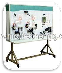
The Instruction board adopts the real components of Central door Locking and alarm system to illustrate Locking and safety system structure and working principle. The components are rigged onto colour circuit diagram. And made functional.
Features
Real and operatable Central door Locking and alarm system is assembled onto a colour printed board to illustrating the structure and working process .
Coloured circuit diagram on the training Module printed on to 6mm organic glass base. Where in the students can compare the diagram and actual diagram.
Detection terminals for operator to detect various sensors, actuators, electrical signals for engine control unit, such as resistive, voltage, current, frequency and wave form signals are provided on to the printed circuit diagram.
Fault setting switch bank will be provided to induce faults in the training module to demonstrate the fault and to diagnose faults. n circuit faults can be induced, user can adjust the number and type of faults.
Set the line break, grounding short circuit, improper contact or ope
Good working condition Parts will be provided with fuel tank. The instruction board has to be connected to 220V AC socket Which changes to 12V DC internally, so that the board works without battery.
The training module is fabricated using steel pipe frame with spray painted for good looks and the entire setup is provided with caster wheels with brakes for easy movement of the same.
Empowering Automotive Education
This instructional laboratory board enhances automotive electrical teaching by simulating central door locking and alarm mechanisms as found in modern vehicles. The multicolor panel features clear diagrams, color-coded wiring, and real lock/unlock switches. Its manual and fault simulation modes allow students to visualize and engage with real circuit behavior, promoting deeper understanding of car security systems.
Hands-On Learning and Demonstration
Designed for technical students (18+), this unit provides direct interaction with actual components such as actuators, controllers, and sirens. With LED indicators and buzzers, users can observe the complete process of door lock/unlock and alarm activation. The board offers both wall mount and tabletop configurations, making it suitable for diverse classroom layouts.
Designed for Practicality and Serviceability
Every module and connector on the board is easily accessible and replaceable, allowing hassle-free maintenance and repeatable fault-setting experiments. The sturdy, powder-coated laminated metal construction ensures classroom durability, while the ready-to-use assembly with a desktop stand simplifies setup and use. Clear test points make diagnostic exercises straightforward and effective.
FAQs of INSTRUCTION BOARD FOR CENTRAL DOOR LOCKING AND ALARAM SYSTEM:
Q: How does the Instruction Board for Central Door Locking and Alarm System help in learning automotive electrical systems?
A: This board enables hands-on experience with central door locking and alarm circuits, simulating real car components and operations. Students can observe and control the locking/unlocking process and alarm activation procedures, reinforcing theoretical knowledge with practical demonstration.Q: What components are included with the instructional board, and how are they organized?
A: The board comprises a central locking actuator, electronic alarm circuit, manual and simulated control switches, door controllers, color-coded wiring harness, fuses, test points, and LED indicators. All components are securely mounted and clearly labeled for easy identification and use during training sessions.Q: When and where is the instructional board ideally used?
A: It is best used during automotive electrical training sessions in technical institutes, vocational schools, or engineering labs. Its flexible mount (wall or tabletop) and compact dimensions (700 mm x 600 mm x 100 mm) make it suitable for standard classrooms or dedicated automotive labs.Q: What is the process for using the board to demonstrate central locking and alarm functions?
A: Connect the 12V DC external power supply, select manual or simulation control, and use the provided switches to lock or unlock the model doors. The system will show the process with LED indicators, actuators, and audible alarm feedback. Faults can also be introduced for diagnostic practice.Q: How does the board facilitate fault simulation and troubleshooting exercises?
A: Users can deliberately set faults using built-in switches and connectors to disable specific components or circuits. This allows students to diagnose and resolve real-world problems, enhancing troubleshooting skills in a safe environment.Q: What are the key benefits of this instructional board for students and teachers?
A: It offers easy visualization, active participation, and repeatable practice with real automotive circuits. Teachers benefit from ready-to-use demonstrations, while students gain hands-on skills, fault diagnosis techniques, and a strong grasp of electrical principles.Q: Where is the instructional board manufactured and what materials are used?
A: The board is manufactured in India, using a combination of laminated metal sheet, durable plastic parts, and PCB mounts. The surface has a powder-coated finish and a UV-printed instructional diagram for longevity and clear visibility.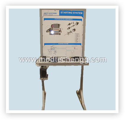
Tell us about your requirement

Price:
Quantity
Select Unit
- 50
- 100
- 200
- 250
- 500
- 1000+
Additional detail
Mobile number
Email

More Products in Instruction Boards/Training Platforms Category
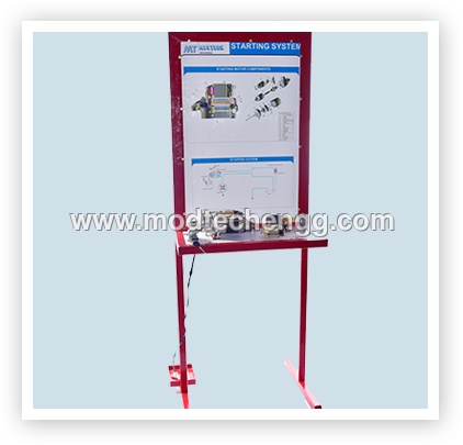
INSTRUCTION BOARD FOR STARTING SYSTEM
Price 2000 INR
Minimum Order Quantity : 1 Unit
Power Type : No electrical power required (manual demonstration)
Age : Suitable for all training ages (technical students and mechanics)
Color : Multicolor panel with highlighted circuits
Features : Labeled components, clear print, easy wall mounting, educational purpose
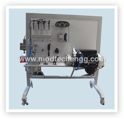
ELECTRONIC FUEL INJECTION SYSTEM OF DIESEL ENGINE
Price 200000 INR
Minimum Order Quantity : 1 Unit
Power Type : Electric Powered (220V/50Hz AC)
Age : Adult (for technical education and professionals)
Color : Silver, Black, and Yellow
Features : Sensor integration, realtime display, modular build, safe handling
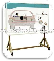
REVERSE CAMERA AND PARKING ASSIST SYSTEM
Price 2000 INR
Minimum Order Quantity : 1 , , Unit
Power Type : 12V DC (Vehicle Battery Powered)
Age : Universal for all ages of vehicles
Color : Black (Standard)
Features : IR LED Night Vision, Grid Marking, Water Resistant, Shock Proof, Wide Angle Lens
INSTRUCTION BOARD FOR IGNITION SYSTEM
Price 2000 INR
Minimum Order Quantity : 1 Unit
Power Type : Manual Display (No Power Required)
Age : For engineering students, 18 years and above
Color : Multi Color Print
Features : Detailed labeling, Colorcoded wiring, Component names, Portable
Our Products
- Cut Section Complete Chassis With Electricals
- Cut Section Complete Chassis Without Electricals
- MODEL OF ENGINE ASSEMBLY WITH CLUTCH & GEAR BOX
- CUT SECTION MODEL OF ENGINE
- Engine Assembly with Clutch & Gear Box
- CUT SECTION MODEL OF TWO STROKE SINGLE CYLINDER DI
- Cut section Model Of Gear Box
- Cut section Model of Steering Gear Box
- Cut Section Model of Clutches
- Cut Section Model of Differential with Rear Axle
- Cut Section Model of Brake System
- Cut Section Model of Electrical System
- Cut Section Model of Fuel Supply System
- Cut Section Model Of Suspension System
- Cut Section Model Of Lubrication & Cooling System
- Cut Section Model Of Different Small Components
- Four Stroke Petrol Carburettor Engine For Practice
- Four Stroke Petrol Mpfi Engine Setup For Practice
- 4 Stroke Petrol Carburator Engine With Lpg Setup
- Four Stroke Petrol Mpfi Engine With Lpg Setup
- Four Stroke Diesel Engine Setup
- Two Wheeler Petrol Engine Of Running Condition
- Instruction Boards/Training Platforms
- Training Module For The Engines
- Test Rigs
- Cut section model Of Complete Vehicle
- Cut Section Model Of Engine Working
- Cut section Model Of Different Automobile Parts
- Cut Section Model Of Two Wheeler Aggregator
- Practice/ Running Engine Setup
- Tool And Equipments
- Model Of Auto Electricals
- Garage Tools & Equipments
- Cut Sectioned Engine Assembly With Clutch & Gear
- Exhibition Models

Plot No. 95, Behind Omex Auto, Bommasandra Jigani Link Road, Jigini Post, Bengaluru - 562105, Karnataka, India

Mr Sunil J.
(Partner)
Mobile :08045479896
 Send Inquiry
 Send SMS
Developed and Managed by Infocom Network Private Limited.
